
Oldham MX 40 Controller for BM25 Wireless Gas Detectors
- Home
- Products
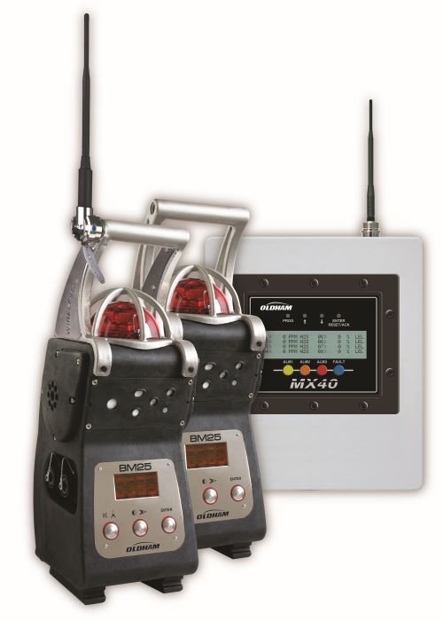
Oldham MX 40 Controller for BM25 Wireless Gas Detectors
The MX 40 is a gas detection unit that communicates via radio to the BM 25 wireless units. This allows for the centralisation of all of the measurements recorded by the BM 25s in one location and the adjustment of settings.
The MX 40 controller can manage up to 16 wireless BM 25 units, including up to 32 measurement channels. A unit equipped with LEL, NH3 and O2 cells will occupy 3 measurement channels. Therefore, a maximum of 10 units of this type could be connected to the same MX 40.
The technology used is a mesh network. All hosts are interconnected with this type of network, forming a net-like structure. Each network node can receive, send, and relay data. This avoids the problem of sensitive points in the network, which would cut the connection to a part of the network in case of an outage. If a node is out of service, the neighbouring nodes will relay the messages via another route.
The maximum range between network nodes is 1000 meters, open-field. Because the same message can be relayed 4 times, the maximum distance between a node and an MX 40 unit can reach up to 5000 meters.
The frequency is 2.4 GHz. This frequency is the most popular because it is license-free in most places worldwide, unlike the 868 MHz and 900 MHz bandwidths. To be precise, communication is carried out on the ISM (Industrial, Scientific and Medical) radio band, which is located between 2.4 and 2.4835 GHz.
The I/O modules communicate over the MX 40’s RS485 network. They are mounted on the DIN rail on the MX 40 enclosure or may be located remotely, up to 1000 meters from the controller.
| Model / Code | Description |
|---|---|
| M954-X | MX40 control system in NEMA 4X Stainless Steel enclosure |
| 08 |
Eight wired sensors with power supply Dimensions (W x H x D): 300 x 350 x 173 mm 11.85″ x 13.75″ x 6.79″ |
| 32 |
Thirty two wired sensors with power supply Dimensions (W x H x D): 405 x 455 x 215 mm 16″ x 17.85″ x 9.5″ |
| 0 | No audio visual alarm |
| 1 | Horn only |
| 2 | Red alarm indication |
| 4 | Amber alarm indication |
| 5 | Green alarm indication |
| 6 | Blue alarm indication |
| 7 | Purple alarm indication |
| 9 | Clear alarm indication |
| A | Red alarm with horn |
| C | Amber alarm with horn |
| D | Green alarm with horn |
| E | Blue alarm with horn |
| F | Purple alarm with horn |
| G | Clear alarm with horn |
| 2 | No battery backup – Stainless Steel enclosure |
| 3 | Battery backup – Stainless Steel enclosure |
| 4 | 320 series transceivers (master) |
| 5 | Two transceivers (master and slave) |
| 8 | Normal display |
| 1 | Antenna separation kit including 7db antenna and 10m cable |
| MX 40 Spare Parts | |
| DET-975-041400-000 | Model RL4 relay module |
| DET-975-041402-000 | Model DI-4 four channel dry contact input module |
| DET-976-041400-000 | Model DA-4 four channel 4-20 mADC input module |
| DET-975-041401-000 | Model AO-4 four channel analog output module |
| DET-898-XANMNM-000 | Adapter for mounting high gain antenna to box |
| DET-980-NTNT40-030 | 10 meter antenna cable for X40 controller |
| DET-976-00132D-000 | Radio module DIN rail mount MX 40 |
| DET-360-ML0100-024 | 24VDC 4.2Amp 100W DIN rail mount power supply |
| DET-327-000000-000 | Programming magnet |
Enquire About This Product
Get in touch with us to see how we can help you with your project