
Drager Regard 3000 Control System
- Home
- Products
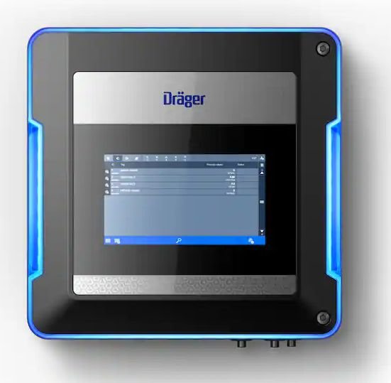
Drager Regard 3000 Control System
The Drager REGARD 3000 control system is a modular gas detection system that can detect various gases and vapours. Its multi-coloured status light indicates the status of the system. You can combine three modules – Input, Relay and Gateway – and connect up to four analogue transmitters and eight relays with the controller.
Especially well visible and audible from a distance
In the event of an alarm, every second counts – but it is also helpful to see the status of the gas detection system at a glance. The REGARD 3000 makes this possible with its status light. Different colours indicate whether everything is in order (blue), whether there are malfunctions (yellow) or whether alarms are pending (red). In addition, it can be seen immediately whether the alarm is active (flashing red) or has been acknowledged (continuous red light). This way, everyone on site is informed about the system status and daily checks are made easier.
Access the gas warning system more centrally
Gas transmitters are often installed in areas that are difficult to access or far away from each other and the associated control unit. The REGARD 3000’s 4 – 20 mA HART® input module gives you central access to all diagnostic information in case of an alarm or fault. The transmitter configurations can also be read out and transferred conveniently. The intuitive touch display gives you an overview of the status of your gas detection system at all times.
Flexible options for expansion
If the range of functions or the size of the gas detection system changes, The REGARD 3000 can be expanded by an additional relay or gateway module, depending on the requirements. This way, the system remains flexible and grows with the plant without shutting down the production process for longer. A REGARD 3000 can be equipped with a maximum of one input module, one relay module and one gateway module.
Networking individual systems with each other
Do you have several gas detection systems with REGARD 3000 and REGARD 7000? Would you like to have all systems in view and control and configure them centrally? Then, connect the REGARD 7000 as a client to the REGARD 3000 systems via an Ethernet cable connection. Networked in this way, the client can detect, control and configure the REGARD 3000 units as satellites.
Flexible options for mounting
Do you already have a control cabinet or control station for your production process control system and would like to integrate the gas warning system there? Or do you need a small gas detection system that can easily integrate into your building? With the Dräger REGARD 3000, you can integrate the docking station directly into a control cabinet and mount the operating unit (display module) in the control cabinet door. Or you can use the innovative, compact wall-mounted housing. You can choose between the colours telegrey and black.
Order Information
3705684 Drager REGARD 3000 Base unit black
3706357 Drager REGARD 3000 Base unit grey
3709719 Drager REGARD 3000 Display unit black
3705685 Drager REGARD 3000 Display unit grey
3705672 Drager REGARD 3000/5000 Slot Cover
3705680 Drager REGARD 3000 4 – 20mA Input Module 2Ch
3705681 Drager REGARD 3000/5000 4 – 20mA Input Module 4Ch
3705687 Drager REGARD 3000/5000 Relay Module 4Ch
3705688 Drager REGARD 3000/5000 Relay Module 8Ch
3705693 Drager REGARD 3000/5000 MB RTU Gateway Module
3705694 Drager REGARD 3000/5000 MB TCP Gateway Module
3711953 Drager REGARD 3000 Adapter plate Set
3704261 Drager REGARD 3000 Control cabinet cable harness 2 m
3709678 Drager REGARD 3000 Docking Station
3716409 Drager REGARD 3000 Dust cover
3716411 Socket spanner for cable gland
3720165 Drager REGARD 3000 Fixing bracket
3709533 Drager REGARD 3000/5000 PC-Software Key
| Parameter | Specification |
|---|---|
| Control Unit Characteristics | |
| Type of Controller | Modular control unit for gas and fire warning systems for wall or control cabinet mounting |
| System Boundaries | 1 Docking Station, 1 Input Module, max. 1 Output Module, max. 1 Gateway Module, max. 1 Configuration PC |
| System Response Times |
Transmission of measured values and status information to the
REGARD® 3000 If maximum transmission time for status information is exceeded, a special status is signalled Measured value update time at input: 50 ms (4–20 mA Input Module / HART® 2/4 Ch) Measured value update time at input: max. 6 s (Modbus RTU Gateway Module) |
| Setting Times |
t20 < 3 s t50 < 3 s t90 < 3 s Independent of measured gas |
| Time Until Ready to Measure | After switching on the REGARD® 3000: < 60 s |
| Electrical Data | |
| Terminal Blocks | Plug-in contacts for conductor diameters from 0.08 mm² to 2.5 mm² |
| Operating Voltage | 115–230 V AC, 50–60 Hz |
| Power Consumption | 2 A max. (typically 1 A), depending on installed modules and connected transmitters |
| Power Loss | Max. 25 W (10 W power supply + 15 W docking station) |
| Output SFR | Min. 5 V, 10 mA, max. 30 V, 2 A switching capacity; fuse output against overload |
| Output SSR | Min. 5 V, 10 mA, max. 30 V, 2 A switching capacity; fuse output against overload |
| Pre-Alarm Relay Output | Min. 5 V, 10 mA, max. 30 V, 2 A switching capacity; fuse output against overload |
| Master Alarm Relay Output | Min. 5 V, 10 mA, max. 30 V, 2 A switching capacity; fuse output against overload |
| Monitoring Functions |
Input voltage monitoring (18–30 V) Undervoltage activates SFR Overvoltage switches supply off and activates SFR Total current monitoring: shutdown at >5.5 A (max. 6 A) Overtemperature monitoring with docking station shutdown and SFR activation |
| Terminal Blocks | |
| Terminal Type | Plug-in terminal |
| Conductor Diameter | 0.5 mm² to 2.5 mm² |
| 4–20 mA Input Module / HART® 2/4 Ch | |
| Number of Input Channels | 2 or 4 |
| Transmitter Supply Voltage | Typically 24 V, depending on docking station supply voltage |
| Transmitter Supply Current |
Max. 500 mA per channel Total max. 1 A per module (≥50°C) Total max. 2 A per module (<50°C) |
| Current Range Signal Input | 0 to 24 mA (short-circuit detection at 38 mA) |
| Input Resistance | 262 Ω |
| Measurement Accuracy |
±0.05 mA ±0.002 mA/K (0–4 mA) ±1.25% ±0.05%/K (4–24 mA) |
| Power Consumption | Max. 2.1 A |
| Power Loss | Max. 5 W at 24 V |
| Deviation with Adjustable Time Parameters | Max. ±1% |
| Relay Module 4/8 Ch | |
| Number of Output Relays | 4 or 8, each with one potential-free switch contact |
| Switching Voltage |
100–240 V AC, 50–60 Hz 5–50 V DC |
| Switching Current |
100–240 V AC up to 2 A (cos φ ≥ 0.4) 5–30 V DC: 10 mA to 2 A >30–50 V DC: 10 mA to 1.2 A |
| Power Consumption |
Max. 100 mA (no relay activated) Max. 150 mA (4 relays activated) |
| Power Loss | Max. 5 W at 24 V DC |
| Pollution Level | 2 |
| Overvoltage Category | II |
| Update Rate of Switching Outputs | 0.5 s |
| Deviation with Adjustable Time Parameters | Max. ±1% |
| Modbus RTU Gateway Module | |
| Number of Channels | 1 bidirectional channel; occupies one system port |
| Current Consumption | Typical 100 mA at 24 V |
| Power Loss | Max. 4 W at 24 V |
| Transmission Rate | Adjustable from 9,600 to 921,600 Baud |
| Cable Length (Fieldbus Side) |
<57,600 Baud: max. 1200 m <230,400 Baud: max. 500 m <921,600 Baud: max. 120 m |
| Housing Characteristics | |
| Dimensions (H × W × D) |
Base Unit: 300 × 305 × 100 mm Display Unit: 300 × 303 × 50 mm Docking Station: 185 × 200 × 50 mm 4–20 mA Input Module / HART® 2/4 Ch: 69 × 110 × 35 mm Relay Module 4/8 Ch: 69 × 110 × 35 mm Modbus RTU Gateway Module: 69 × 110 × 35 mm Slot Cover: 69 × 110 × 35 mm |
| Ambient Conditions | |
| Operating Temperature | -20°C to +55°C |
| Storage Temperature | -30°C to +65°C |
| Humidity (with Display Unit) | 5–90% RH, non-condensing |
| Humidity (without Display Unit) | 0–95% RH, non-condensing |
| Humidity (Storage) | 5–90% RH, non-condensing |
| Pressure | 700–1300 hPa |
| Maximum Installation Height | 2000 m above sea level |
| Approvals | |
| ATEX (Metrological Performance) | EN 60079-29-1, EN 50104, EN 50271, EN 45544-1, EN 45544-2, EN 45544-3 |
| SIL (Functional Safety) | EN 50402, IEC 61508-3 |
| CE Marking |
2014/34/EU ATEX Directive 2014/30/EU EMC Directive 2014/35/EU Low Voltage Directive |
Enquire About This Product
Get in touch with us to see how we can help you with your project